Anymore thought on this?
I need a crown gear and I'd rather not do it the hard way (tooth at a time)....
Thanks,
-james
Crown Gear

Re: Crown Gear
James:
I have been considering it, but I dont see a way to do it.. if the teeth turn outwards on the 4th axis , they get thinner as
you go toward center.. so in essence its a bevel at 90 degree's? Which takes us full circle to finding a proper method to machine a bevel.. One reason so many use crown gears that are very thin toothed I suspect is that really their bevels..at least near as I can see, but I may be being thick..
Art
Re: Crown Gear
On most I see the "lands" between the teeth get wider but the teeth themselves have the same width all the way. The "hooking" of the pressure angle I think is mostly to reduce thrust on the gears, not so much to fill the gap. At least that is what I dimmly recall.
Are you saying its hard from a algorithmic standpoint to get the math to behave right? The same problem you had with helical bevels?
How did the old school draftsmen and machinists do it?
Are you saying its hard from a algorithmic standpoint to get the math to behave right? The same problem you had with helical bevels?
How did the old school draftsmen and machinists do it?
Re: Crown Gear
James:
To me , its a question of math, not how to draw it so much as how you'd machine it on a 4th axis. If a crown has involute teeth,by definition to me its a bevel, each tooth must by its nature get thinner as it gets closer to the shaft center. And there is no angle to reach the parts to cut. 3D printing would be possible, but if you generate a bevel at 90 degrees with a small facewidth in gearotic, isnt that what your reffering to as a crown?.. or as Im picturing what you we're calling a crown gear. Theres a lot of loose definition on a crown..even a google on the type shows basicially ..bevels. And those are really 5 axis entities is one wants to do them in an algorithmic way.. of course 3d engraving them is always possible.. but very slow and now very clean..
Art
Re: Crown Gear
Hi Art, thanks for the reply.
To me this is a simple straight cut crown gear:
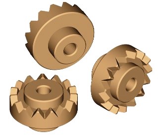
This I guess is also know as a "face gear". But is more practical, and what I am looking to produce:

And this is our friend the helical crown gear:

or:

So yes, I guess it is a bevel flattened out to 90 degrees.
What if you could output the DFX drawing (and resulting the G-code) where the gear is "flipped" flat as a 3 axis job? Sort of the same way as for 3D printing one? I don't see where there would be an unreachable undercut as long as your cutting tool wasn't wider than the narrowest gap between the inner part of the teeth. It would be just like milling any other complex shape.
Sorry if this has been suggested before, I didn't look thru all the other topics for related content. Oh, and I didn't even try to see if the above is supported by Gearotic already. LOL...
To me this is a simple straight cut crown gear:
This I guess is also know as a "face gear". But is more practical, and what I am looking to produce:
And this is our friend the helical crown gear:
or:
So yes, I guess it is a bevel flattened out to 90 degrees.
What if you could output the DFX drawing (and resulting the G-code) where the gear is "flipped" flat as a 3 axis job? Sort of the same way as for 3D printing one? I don't see where there would be an unreachable undercut as long as your cutting tool wasn't wider than the narrowest gap between the inner part of the teeth. It would be just like milling any other complex shape.
Sorry if this has been suggested before, I didn't look thru all the other topics for related content. Oh, and I didn't even try to see if the above is supported by Gearotic already. LOL...
Last edited by Anonymous on Tue Dec 15, 2015 4:05 pm, edited 1 time in total.
Re: Crown Gear
Yup, all essentially 90 bevels, which gearotic does put out. Youll notice in the chrome looking pair the teeth dont look
like a mesh, pinion is involute and the "crown" is triangular. Gearotic will basically put out all those types including the zerol..
but cutting them is a challenge other than simply using the 3d stl like a model to be engraved, but by algorithm, near impossible.. so far as Ive been able to figure out.. and engraving would leave a lot of roughs to deal with from the tool
lines, ( the reason tangent shaving works so well, no tool lines.)
The problem with them is that they really lend themselves only to engraving type of cutting on 3d , not 4th axis as you
cant shave the tangents in 4th axis.
Re: Crown Gear
Pardon my naivitee, but is "engraving" the same as tracing contours with a ball-nose end mill?ArtF wrote: ...
but cutting them is a challenge other than simply using the 3d stl like a model to be engraved, but by algorithm, near impossible.. so far as Ive been able to figure out.. and engraving would leave a lot of roughs to deal with from the tool
lines, ( the reason tangent shaving works so well, no tool lines.)
...
Re: Crown Gear
When I started generating bevel gears, I set them up so that the (idealized) contact line between the teeth would always go through the tip of the pitch cone. That makes the gears symmetric and allows for a system of many different bevel angles that all mesh with each other, but it's not the only option.ArtF wrote:...
The problem with them is that they really lend themselves only to engraving type of cutting on 3d , not 4th axis as you
cant shave the tangents in 4th axis.
Now, let's suppose, instead, that we design a set of bevel gears so that the idealized contact line between the teeth is parallel to the shaft of one of the gears. Then we would end up with an asymmetric bevel gear pair - one of the gears could be an involute spur gear, and we'll call the other one a crown gear.
I need to do some pencil and paper work to be sure that the it works out, but this sort of crown gear should have the nice properties that:
For a 90 degree drive, it should be possible to 'tangentially shave' the tooth flanks using a taper nose end mill and a 3 axis CNC machine (or, for the masochist, even on a conventional 3 axis machine with a rotary table).
It should mesh well with a range of involute spur gears that have the same pressure angle and pitch.
It should be mechanically viable with decent efficiency, little noise, reasonable meshing tolerances and so on.
(This seems like such a good idea that it's probably either wrong, or someone else thought of it well before I did.)
Re: Crown Gear
Hi Nate:
Yes, when I use the term "engraving" I really mean 3 d raster cutting on a plane. It leaves really nasty toolmarks unlessdon ein a tight raster, which is why I resist it so much as a bevel technique. As you your idea of using a
tangent to shaft as the idealized contact point, I cant quite picture how a normal spur can run on a 90 degree bevel, dont the teeth have to narrow toward center?
Thx
Art
Re: Crown Gear
Would tracing geodesics (in particular, geodesics that are close to radial) and restricting the raster to the tooth flanks produce any significant improvement?ArtF wrote: ...
Yes, when I use the term "engraving" I really mean 3 d raster cutting on a plane. It leaves really nasty toolmarks unlessdon ein a tight raster, which is why I resist it so much as a bevel technique.
...
Yes, the teeth have to narrow, but they don't have to narrow along a radius. I need to think about it a bit more, and I'll see about modelling it....
As you your idea of using a tangent to shaft as the idealized contact point, I cant quite picture how a normal spur can run on a 90 degree bevel, don't the teeth have to narrow toward center?
...
Re: Crown Gear
>>Would tracing geodesics (in particula r, geodesics that are close to radial) and restricti ng the raster to the tooth flanks produce any significa nt improveme nt?
Im really not sure, I have tried mental exercises like figuring the effect of only using radial paths from cone center ,
but its hard to say what shape of toolpath would make the toolmarks so they best mesh together without having
to file all day
Art
..
Im really not sure, I have tried mental exercises like figuring the effect of only using radial paths from cone center ,
but its hard to say what shape of toolpath would make the toolmarks so they best mesh together without having
to file all day
Art
..
Re: Crown Gear
Or make the gearsets slightly oversized, put them in a jig, and then run them for a while dry or with a cutting fluid (or even abrasive powders!) to let them "mill themselves". ;)
Re: Crown Gear
:)
That IS one way. Id be interested in peoples experiences having done that. The STL's
and models GM puts out could be used in Vectric and such to generate a path for engraving
type cutting.. I may try that method to see what I get in the new year. Ive designed Auggie
to be able to shut down anytime and resume the next day, so I wont mind so much those
multi hour engraving paths..
Art
Re: Crown Gear
The approach I'd been originally thinking of seems to involve undesirable undercuts.
How about using "improved peg gears" as crown gears?
How about using "improved peg gears" as crown gears?
- Attachments
-
Re: Crown Gear
:)
Think Id prefer two disks, a length of brass rod and just make them from pins..
Even those teeth look like they need to narrow toward center... :)
Art
Think Id prefer two disks, a length of brass rod and just make them from pins..
Even those teeth look like they need to narrow toward center... :)
Art
Who is online
Users browsing this forum: No registered users and 63 guests