Arduino based Laser Control
Re: Arduino based Laser Control
Thanks for the info, by the way my laser isn't actually a Chinese laser its basically a cnc machine with a laser tube it runs off mach3 it has regular stepper motor drivers, not the motion controller like the chinese ones. The inputs on the laser power supply ares as follows: "H" for logic high active, "L" for logic low active, "P" for water pump safety, "G" ground, "In" power level input 0-5v, and "5volt"

Re: Arduino based Laser Control
Dan:
Interesting.. I think the IN is probably a PWM input as well as analogue. I notice that several control circuits
describe their power input as analogue OR PWM, probably because PWM when applied to an analogue input is often
averaged to a voltage level.. so either types of input woudl control it..
A bit of experimentation woudl probably tell you. Of course one could just use the PWM pin on the arduino as an analogue output instead.. might be easier really, no PWM interrupt woudl then be required..
Art
Re: Arduino based Laser Control
yer that would make things faster I am getting this controller to run my 2W 445 diode, FlexMod P3 it says in the manual it needs TTL input: 0-5V for Off-On
0vdc off 5vdc full power controlled from input.
if I remember right I just need an analogue output from 0-255 to run it I am just look up stuff at the moment will get into it full on when the parts arrive at the end of the month the post system is quite bad here something can arived in NZ from china 5 days after it was orded but not get here for up to a month
Re: Arduino based Laser Control
Heres another engraver test, this time in circular mode, I foudn the resolution much better with details I hadnt noticed before coming out. It seems the raster modes erase horizontal details while circular preserves them..
https://plus.google.com/u/0/11833942322 ... 1700707274
Art
https://plus.google.com/u/0/11833942322 ... 1700707274
Art
Re: Arduino based Laser Control
Hi All
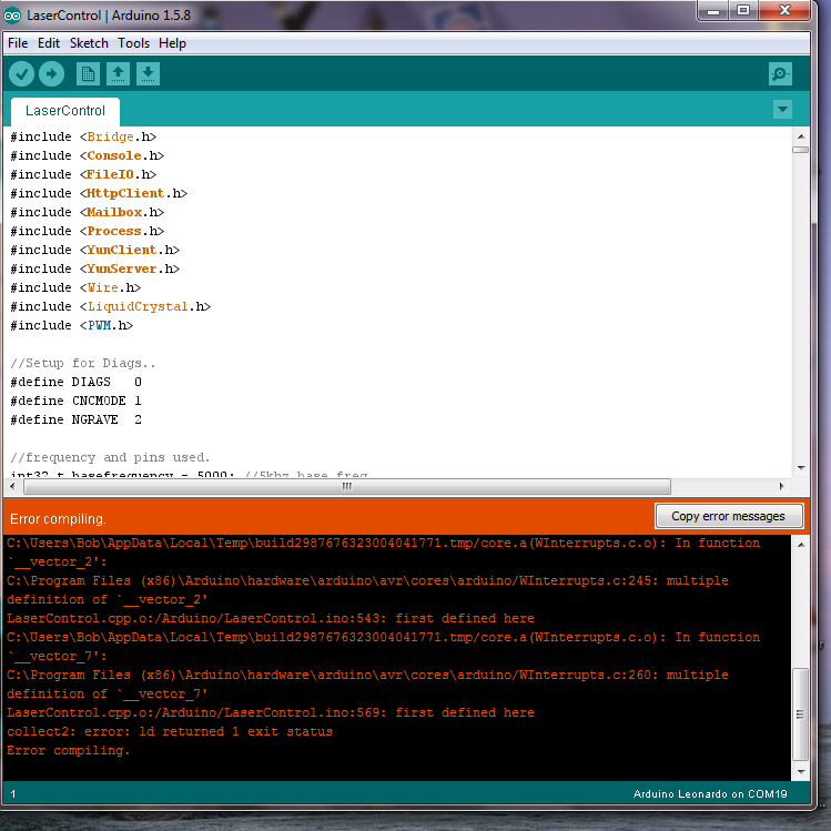
I updated the IDE to 1.5.8
now I get the following.
Danl
when you said you removed all the other bits did you mean just the include lines.
would it be possible for you to post your sketch.
I think I need to start with something simpler.
I am tring to use a 445 laser and ttl on my router.
Thanks
Bob
I updated the IDE to 1.5.8
now I get the following.

Danl
when you said you removed all the other bits did you mean just the include lines.
would it be possible for you to post your sketch.
I think I need to start with something simpler.
I am tring to use a 445 laser and ttl on my router.
Thanks
Bob
Re: Arduino based Laser Control
I am going to be doing the same may be. I wont post to after I know its working properly what will be in a couple of weeks other wise it just gets confusing.
and have you done what art said to do on page one with WInterrupts.c
If you have done that find the temp file and delete the temp files, it can course this problem to happen to, Its the first error shown that's where the temp file is
and have you done what art said to do on page one with WInterrupts.c
If you have done that find the temp file and delete the temp files, it can course this problem to happen to, Its the first error shown that's where the temp file is
Re: Arduino based Laser Control
>>and have you done what art said to do on page one with WInterrup ts.c
Thats the issue. You need to comment out the lines as in the post. I coded in direct
vectors for the interrupts for speed, and the wInterrupts file has to have them rem'ed out...
Looks like your fine other than that..
Art
Thats the issue. You need to comment out the lines as in the post. I coded in direct
vectors for the interrupts for speed, and the wInterrupts file has to have them rem'ed out...
Looks like your fine other than that..
Art
Re: Arduino based Laser Control
thanks lads
bob
bob
Re: Arduino based Laser Control
Hi Guys:
Just thought Id let you know I have modified the laser panels code to change engraving mode
so the pot which controls power for a diagnostics shot now controls the NGrave photo power as well.
Since my photos seemed to only need a power of 20 I was only getting 20 levels at most of power for
the shot, so I implemented a 100 level power array selection in the panel and modified Darwin to send
a power request of 0 - 100% for every step or pixel in the photo. the panel then makes that 0-100% of the
pot's current selected power. This means even if your engraving with 20% max power, that 20% will have
100 levels from 0 - 20%... so .2 percent of laser power per grey scale level in the image.
Im not sure yet exactly how granular my synrad is yet.. it may limit to 1us or 20us..I havent yet tested
but this change should allow for greater grey scale levels that I was getting before. Ill keep you posted.
I wont bother posting code for the changes Im making until others are running a control panel, then Ill
start posting the code Im using and we can discuss better methods when more people are testing.. Ive
also been in touch with Greg for the SmoothStepper and Steve Stallings for the PMDX usb driver for early
discussions on a standard for signal output so no matter what motion device is used with mach, perhaps this panel will work at some point in the future.Any code I use or methods I use I will keep open sourced to maximize the number of people that can engrave using this method of laser control.
Art
Re: Arduino based Laser Control
Hi Art,
I have read all the posts again (and again) and I am still missing the set-up you are using to get the required signals to and from Mach4 / Darwin. :'(
You have shown in your earlier diagram ?step flag", "serial data", "serial clock", "PWM output to laser?, etc. but I really have no idea how these signals are received or sent.
It seems everybody else understands how it has been done but I must have a brain block or something - any chance of a dumbo?s guide to your Mach4 / Darwin configuration please.
Tweakie.
Re: Arduino based Laser Control
Hi Tweakie:
Sorry, my fault really. There should be a full explainatin out there, so here it is as a white paper type of explanation..
To control a laser in Darwin, one can either use a PWM spindle output as in the past for power, or the new serial clk,data and step flags I currently use. So there are basically 3 ways in Darwin to use the laser.
PWM with spindle On/Off:
If one wishes PWM, you simply setup a spindle as PWM and set your spindle range in Mach4 from 0 -100 with ( in my case) 50hz PWM. It all depends on your hardware of course. In the case of the Arduino Laser Panel the 50hz PWM is taken and converted to 5Khz pwm to be sent to the laser. The Spindle On/Off signal is then used to control power on or off, again, depending on hardware. In my case with the Aduino panel there is no need of real time on/off signals as the laser only fires on a step pulse, but one can use M62/M62 commands for rapid on/off ( those commands are untested as of yet and we're waiting on confirmation as to how to use them) if you have on/off hardware of some sort on your laser control.
Serial Data control:
In this control method you need the arduino panel, or hardware that can accept the data provided. In Darwin, output signals 126, 127 and 128 are hardwired to control the serial clk, serial data and step flag. The use of these items are controlled by the "Laser mode" selection in Darwins M4 diagnostics config. When selected, you can use 2 differing modes, Image linked mode, or normal GCode. In Normal GCode, you set the power as above but with no need of PWM. For example, if you execute an M3S50 , youll be telling Darwin to enable the laser at a power of 50%, the power will be sent as 50 to the arduino using the SerialClk and Serial Data lines. There is a protocol to this which can be seen in the arduino code. When the Arduino see's a step is taken it will fire the laser at the requested power. Further to that, Darwin will check to see how many steps are going to be taken on each waypoint. It will adjust the power of the current shot to ensure the power is as close as possible to the power per step on the fastest motion to be seen in the program. For example, if you have a F3000 in the program, Darwin knows that at full speed a 5khz laser will see 1 shot span over say.. 10 steps. Thats simply the movement the gantry will do as the laser takes one shot. So if Darwin sees a waypoint that moves only 1 step, it will reduce the power of that shot to 10%, in this way trying to ensure the line is burned evenly even though your moving slower at the beginning of a line than at the end. SO its important you have Feedrate command before the M3 command as Darwin does its computation of this at M3 time. This is the CNC mode of the arduino panel, its simply fires each step pulse at the power and count of pulses dialed up on the panel with Darwin modifying the power as above.
NGrave mode:
The NGrave mode is Darwins Photo only mode. In this mode you link a photo (In Darwins Diagnostics menu). This photo linkage will load G code at the same time as it links to an image data file created by the same dialog. ( Or by gearotic which can manipulate the gray scales in various ways to enhance the engraving by matching power levels to various mathematical curvatures that reflect true power dissipation in various materials. ). The G code put out by the image processor may be manipulated by the user in any way he wishes, it is not critical. The way it works is that Darwin will monitor all motion while in linkage mode, If the current position of the axis are within the size of the photo data file ( you specify in inches or mm's the actual size of the engraving at creation time), Darwin will look into the photo file, find a power level ( 0 - 100% from the 0-255 grey scale) and send it via serial data to the arduino. The arduino will then find a power level from 0-100% of the currently selected maximum from the pot on the panel. For example if the panel has selected 50% power and Darwin send 50%, then 25% will be put out for this current set of way-point steps. If 100% was selected on the panel, then 50% power would come out. The power for NGrave is not yet corrected as the previous method to correct for acceleration, which is why the RAMP selection is available for image file creation, this RAMP variable tells the G Code generator to add motion before and after a photo line to allow the gantry to come up to stable speed so the photos power is consistent across the image. This cannot be done in Spiral mode though, so eventually I will likely do a correction as in the previous mode for way-point distance power correction. Spiral mode allows for greater resolution, one of the problems with raster engraving of an image is that constant linear motion has a tendency to remove or burn out linear image information which occurs naturally in many types of images. In the end its likely a much better G Code routine could be created to give high resolution in some areas and lower in others to speed up the process of making an engraving. For example one could simply not scan white area's.. we'll see what the future brings... If the axis are outside the image boundaries in NGrave mode, zero power level is sent to the arduino panel and the laser is not triggered.
Hope this all helps, ask any questions you like, Im hoping this laser project will be community driven and good ideas from any quarter are appreciated, this is all an area which requires a vast amount of experimentation, both in code and materials/Power.. ( thats what makes it fun. ). That having been said I know making something like an Arduino panel takes time , initiative and desire, so until others have one, Ill continue to play with mine and the code base will morph over time. I wont publish such code changes till such time as others have the original panel working so as to not confuse the issue.
Thx
Art
Re: Arduino based Laser Control
Hi Art,
Thanks for the detailed explanation - it is all much clearer now.
The Output Signals 126, 127 & 128 was the key part I was missing. ;)
Tweakie.
Thanks for the detailed explanation - it is all much clearer now.
The Output Signals 126, 127 & 128 was the key part I was missing. ;)
Tweakie.
Re: Arduino based Laser Control
Tweakie:
Good. I stuck the signals up there because Mach4 users can access only the first 64 signals of input or output. Darwin was written for Mach4 , it was written to be generic, its why its capabilities arent all used by Mach4. M4 use is limited to 4 axis, 64 inputs and 64 outputs, so when I have something special to add I'll always use the upper end of the range.
The protocol is a simple one and unidirectional. 0xfnnf is sent, with nn being the hex control byte. ( 0-100 in decimal) and the byte must be received identically twice before being considered valid. That will probably change if I ever upgrade to a faster processor like a beagle board or something where I could really get complex. :)
Art
Re: Arduino based Laser Control
Hi Art,
I have just looked at Output Signals 126, 127, 128 - I had to configure them to output pins on Port 2 (all outputs on Port 1 are taken) but as yet I am not getting anything at all showing up on the scope. :'(
I will have a look again tomorrow and see if I can discover what it is that I am not doing right. :)
Tweakie.
Re: Arduino based Laser Control
Hi Tweaky:
Port shouldnt matter.. it has to be enabled of course, but the port shouldnt matter.. I have only 1 so its hard for me
to test that..but I have checked the code just in case. All "looks" well.
Steve confirms the M62/M63 has broken, a fix is underway on that as well.
Art
Port shouldnt matter.. it has to be enabled of course, but the port shouldnt matter.. I have only 1 so its hard for me
to test that..but I have checked the code just in case. All "looks" well.
Steve confirms the M62/M63 has broken, a fix is underway on that as well.
Art
Who is online
Users browsing this forum: No registered users and 0 guests